Wednesday, January 20, 2010

43) Get wired!

Photo
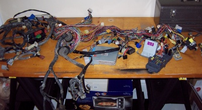
This mess of wires is what I pulled from the donor Legacy. I know it's not necessary to get every wire from the Suby, but I wanted to be sure I could trace every wire needed. For example the tach and speedometer wires end up in the dash harness, and go to the speedo cluster.

Photo
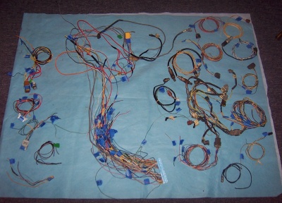
This is after extracting each wire from the ECU. I unwrapped all the black corrugated piping and electrical tape. What a sticky mess that was!

Photo
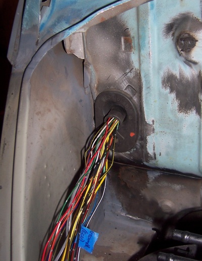
Here's the Suby firewall grommet that I'm reusing. I fed each wire through it while I was shortening each ECU wire -> sensor or plug. I soldered each wire, and used a glue type shrink wrap to seal it all up.

Photo
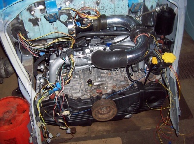
Here I'm measuring the length of each connection. I wanted to get the lengths roughed in before I solder everything in and reapply all the wire protection.

Labels:

Saturday, November 7, 2009

42) Alternator belt

Photo

With the new alternator bracket in place, I now had a bit of an issue with finding the right belt that would fit. This belt was too tight, and wouldn't fit with the alternator adjusted as low as it could go. The next belt size up was too long and the alternator didn't have enough adjustment to make it tight.

Photo

I then decided to get a set of smaller pulleys to see if my smallest belt would fit.

Photo

No luck, the smallest belt now is too big for these small pulleys.

Photo

I finally found a belt that was the perfect length, and allowed me to tighten it right about midway through the adjustment of the alternator! The only possible problem here is that this belt has skinnier then the OEM belt. I'm guessing that since this is only driving the alternator that it should hold up fine :) *Fingers Crossed*

Labels: ,

Sunday, July 12, 2009

41) Alternator Bracket

With the rotated coolant manifold the stock location of the alternator no longer works. Slowly, I built up a bracket that would bolt into the location of the old power steering pump. I mostly used 3/4" square tubing, with a few pieces of spare metal that I had laying around also. (There are some pieces of old bumper brackets and bed frame angle iron in there :)

Photo
This is the pivot side of the alternator. I needed to make sure the oil pressure sensor and throttle body preheater hose would fit around the bracket.


Photo
This is a mock up of the adjustable side of the alternator. The OEM bracket bolts from the other side, but I'm planning to bolt through in this direction because it is less fabricating and material needed.

Photo
This is the front side of the adjuster. You can see here it adjusts like normal, just from the other side. I had to pay a lot of attention to the min and max adjustments of the alternator to be able to get the most travel possible. I ended up having to grind down the intake and alternator a bit to get even more travel.

Photo
This is the roughly finished bracket (minus paint of course). I added some gusseting to make a little more rigid.

Photo
Finished and alternator mocked up. Next up will be to find a belt that fits!

Labels: ,

Thursday, April 30, 2009

40) Air filter bracket

Photo
Here's the template and the initial fabricated bracket that will hold the air filter to the firewall.

Photo
Here I've ground down the welds, and cut a super lightweight "Racing" hole :)

Photo
I'm welding in some studs to the firewall so this can bolt up easy. The attachment to the MAF tube is where it all connects up. I actually can't decide between welding in studs or nuts. Any recommendations?

Photo
Here's what it looks like all bolted up. The air filter and MAF will stay solid to the car and with the help of the bubble connection (not showing here) in the middle, the rest of it will move with the motor.

Labels: ,

Saturday, April 11, 2009

39) Air intake fittings

Since I ditched the stock air intake and assembled a custom one using aluminum piping, I needed a way to connect all the tubing that goes between the air intake and various parts of the motor.

I decided I would try out some quality Home Depot engineering :) Not sure if these will work or not, but it was easy enough to do and didn't take too much time (Aside from the hours strolling through HD looking for bits and pieces!)


Photo
First comes drilling the holes. Have I mentioned how much I love these stepper bits?


Photo
Next I stuck a end cap through the hole.


Photo
After boring a hole through the end cap, I made a grommet out of a section of rubber hose. I shaped the rubber so it would fit the curve of the intake tube, and left the top flat.


Photo
Then I tightly screwed on the barbed fitting.


Photo
Here is the forward most section with a couple more fittings.


Photo
Here is the rear section test fitted to the IAC (Idle Air Controller)


Photo
Another shot of the forward section all plumbed up to the valve covers & crank case breather.

Wednesday, April 8, 2009

38) Room to bleed (breath?)

I thought it would be a good idea to add a breather to the top of my coolant manifold so that bleeding the system would be easier. Coolant will be raising up to the manifold via pipes that will be running low in the chassis (More on this later) I will screw in a valve here to open as I add coolant to the system.

Photo
This is the tap I used (1/8"-28 NPT)

Photo
This is the valve I'm going to put in there.

Labels:

Thursday, April 2, 2009

37) Cleaning up engine parts

Photo
Took some time to clean up some rusty engine parts. I know I'm missing some stuff in here, which I'll get with another batch some other day :)

Photo
Sand blasted!

Photo
All painted!

Labels: